
Image Courtesy of UPPAbaby Marketing
UPPAbaby MESA Max
Skills Used: Industrial Design, User Research, Form Development, Visual Branding, 3D Printing, SolidWorks, SketchBook Pro, Photoshop, Keyshot
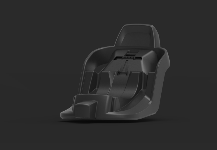
The MESA Max car seat was released to the North American market as UPPAbaby’s premium infant seat. I worked with the lead industrial designer and several engineering resources to bring the MESA Max base to the market. The design of the Load Leg, Control Panel, Touch Points, Manual Storage, Latch Connector, Lock-Off Doors, Recline Handle and Belt Path were my main contributions.
Project Scope & Product Architecture
01: Safety Features
Newer safety features have been developed since the release of the original MESA car seat. The scope of the project required these features to be added into the new base along with findings from crash simulation.
02: Surface Limitations
Certain surfaces of the base were fixed in place to maintain the relationship between the base and child carrier. In-addition it was fundamental to keep certain locking, rotation and mounting locations in there required areas.
03: UPPAbaby VBL
UPPAbaby products incorporate the use of primary shapes with soft rounded edges and angles in the architecture of the product. It was necessary to include these design details into the MESA Max.
Baseline Geometry
Fixed Product Architecture

Load Leg: A load leg was added to the MESA Max base. The load leg pivot point location, angle and height were locked into place.

Mounting Locations: The mounting rods needed to stay in their fixed locations in order to remain compatibility with the carrier.

Carrier Surface: The height of the top surface had to stay in place to keep the compatibility with the carrier and to maintain safe crash performance.

Anti-Rebound Bar: A rebound bar was added to the base. The height, angle and location of the ARB was fixed in place to optimize crash performance.
Load Leg Storage Exploration

Load Leg Cover Exploration

Touch Point Exploration

Control Panel & ARB Exploration


Lock-Off Exploration

Latch Connector Exploration

Form Development
Do to the complexity and strict surfacing parameters a majority of the form development was done in SolidWorks. 2D Sketching was used to quickly ideate and refine design details in localized areas.
_.jpg)
CAD Refinement & Prototyping
To develop the MESA Max base, multiple full scale prototype were made to validate the form, volume, mechanics and general functionality of the base. The physical prototypes allowed us to identify areas of improvement that we could further refine.

CMF Process
I was responsible for developing and creating the color, material and finishes of the MESA Max. I worked closely with the engineers to make sure that the surfaces on the parts had enough draft to apply the correct texture.


Images Courtesy of UPPAbaby Marketing


Folding Load Leg
A folding load leg was added to the base to improve the stability and energy absorption. It was my responsibility to design the foot mechanism, extrusion profile, rotational cover and touch points of the load leg.
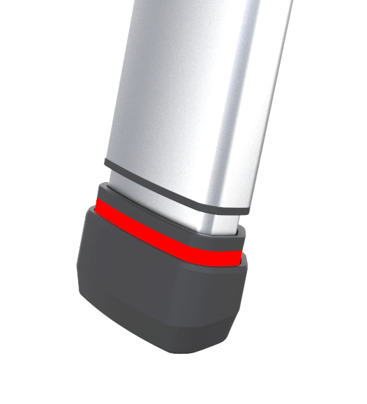
Foot Indicator
The outer sleeve of the load leg foot must fully cover the red strip to achieve a proper install. The inner sleeve has a red colored over-mold. The red over-mold indicates that the foot isn’t fully compressed indicating an incorrect install.


Deployment Indicator
A green and red indicator was designed to ensure proper load leg installation. I had the opportunity to design the sliding mechanism for the load leg indicator. The indicator travels on two vertical posts and is activated by the rotation of the load leg.


Enclosed Pivot
The rotational point of the load leg is fully enclosed to eliminate a pinch or shear point. It was my role to design the cap and shape of the rotational insert and cover.


Belt Path & Latch Connector
To prevent an incorrect install the latch connector and belt path were placed in the same vertical column. This prevents the user from using both features at the same time resulting in an incorrect base install.


Anti-Rebound Bar
The shape of the ARB mimics the shape of a vehicle headrest to signify the correct positioning. The design also incorporates a "reverse waterfall" in the negative surface to break up the large area and follows the UPPAbaby VBL.

Brand Language
Large primary shapes were placed through-out the design of the base. These design details give the product the UPPAbaby look and feel.


Control Panel
A large negative space was placed around the SmartSecure indicator to provide label space and to visually connect the panel to the rest of the base.
In-mold hooks were also designed in to to control panel to capture the seat belt.
